In an oblique drawing all of the following angles are commonly used for drawing the depth axis except. 1- Horizontal line- to draw a horizontal line from a certain point just put the T Square on the edge of the drawing table and move the T Square up and down to reach the certain point and then draw the horizontal line.

Over Engineered Miter Saw Station Plans Etsy Mitre Saw Station Miter Saw Engineering Design Process
Whatever area you will.

. Engineering Drawing MCQs and Answers Set-VI. Drawing a plan I want to achieve the following results when plotting particularly with thick lines. This line is similar to the Dash Thin Lines with Dots except that it has double dots within it.
You would create the weld based on the instructions under the reference line. The section lines should be evenly spaced and of equal thickness and should be. These symbols are usually found in fabrication and engineering drawings.
Two widths of lines are typically used on drawings. This technique may be used to transfer depth measurements on computer drawings. Sometimes you will need to work on separate views and project lines to each other to fully complete any view.
In technical Engineering drawings each line has a definite meaning and is drawn in accordance to the line conventions as illustrated in the figure below. As already said such a technical drawing has all the information for manufacturing a part or welding and building an assembly. Arrowhead Lines are used.
Computer Science questions and answers. If you need help with weld symbols and welders we have an. Question 5 4 points What is purpose of creating a 45 Miter Line in a multiview drawing.
Miter line is used to ensure the alignment of the three views. It is often the case that a two-view projection is all that is required. Allows us to actively control the placing of the.
Application size range can vary from company to company. For drawing the orthographic views for a straight lined when inclined to both Principal Planes go through this linkhttpyoutubeZKahCPO_9WI. Section lines are drawn as thin 35 mm black lines using an H or 2H pencil.
Drawing Techniques The general purpose cast iron section line is drawn at a 45-degree angle and spaced 15 mm to 3 mm or more depending on the size of the drawing. As a general rule use 3mm spacing. The Purpose of Engineering Drawings.
The numbers of cut will be a maximum of 5. The info includes dimensions part names and numbers etc. A right side view tells you everything you need to know.
The thick line width should be 06 mm and the thin line width should be 03 mm. It is obvious that a top view of this object tells you everything you need to know except the thickness. Poor strength because of the more number of joints.
Example Start with the front view The edge C cannot be seen but is. Non-isometric lines are located and sketched how. Example Represent the shown component using multiple view representation.
So once a manufacturing engineer gets the drawing he can start the production process without a second thought. Engineering Drawing WELCOME TO. A weld symbol would differentiate between two sides of a joint using arrows and the spaces on top and under the reference line.
They are lines with pointed edges at one or both ends. These steps are illustrated in. - When a thick line ends at right angles to a thin line I want it to Butt to the thin line.
The view at the top of figure 5-19 shows a single-view projection of an object. Create what is call a MITER LINE this 45 line will be used to project hence Orthographic Projection lines from the TOP view to the RIGHT SIDE view or visa versa. The miter line technique may be used on two dimen-sional CAD drawings.
The pointed edges are in the form of an arrow. In an oblique sketch of a cube. At the end of dimensional lines.
Visible Line Hidden Line Cutting-Plane Lines Center Line. One and Two-View Drawings. Limitations of Miter Bend.
This technique is used on drawings created with T-squares or drafting machines. One method of drawing an ellipse that represents an isometric pictorial circle is known as. A miter line may be used to geometrically transfer depth from the side-to-top and the top-to-side views.
Allows us to draw lines at 450 allows us to transfer measurements in between the top view and the side view allows us to draw two parallel lines at a distance of 45 units. It is used for ghost outlines and bend. Miter option on thick lines - Plotting.
Unfortunately using Butt Miter Butt seems to win the argument at joins and creates a staggered join. Note carefully that the MITER LINE is drawn from where the lower TOP View line and left RIGHT View line intersect. Miter bend can be fabricated with 2 3 4 5 miters.
A miter line is a 45 degree line draw between the top view and right side view by extending out a line on both view and connecting them. The numbers of miters will be decided according to the pressure and temperature of the line. The Miter Line and Projection Lines The use of a 45 miter line and Projection Lines provide a quick accurate method of drawing the other views once one view is completed.
Pin On Oktatas

Pin On Formula

Pin On Autocad

Sample Midterm Problems Engineering Graphics In Design Midterm Design Isometric Drawing

Solidworks Tutorial Anvil Youtube Solidworks Tutorial Mechanical Engineering Design Solidworks

Get Stronger Miter Joints Diy Projects Engineering Mitered Backyard For Kids
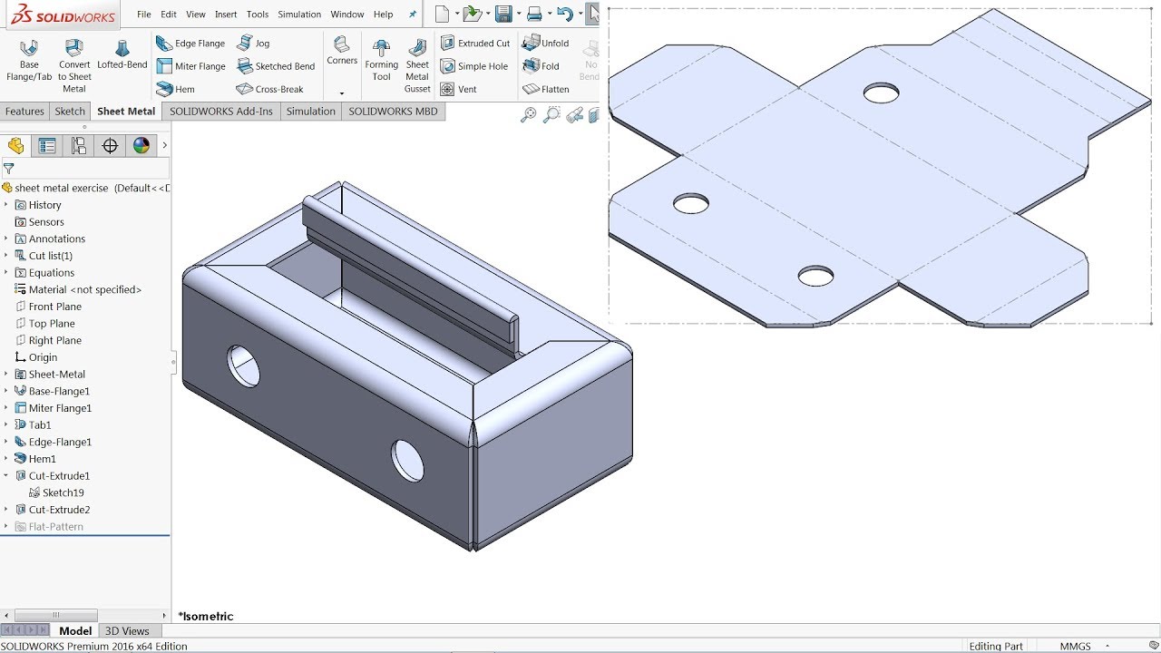
Pin On Solidworks

Over Engineered Miter Saw Station Plans Etsy In 2022 Mitre Saw Station Miter Saw Engineering Design Process
0 comments
Post a Comment